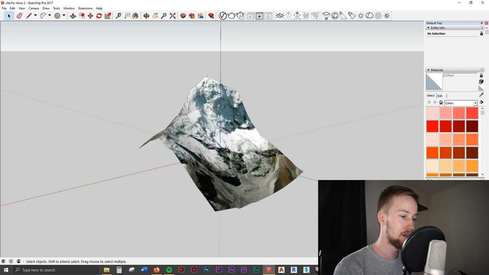
Does anyone have any info about the current state of RhinoTerrain? Apparently they haven't ported their plugin to Rhino 6 nor even to 64 bit Rhino 5. At the moment they don't seem to be answering emails either. Are they still in existence? The creator used to be active on this forum. Claude Vuattoux, are you out there??!! We need a good terrain software for use by students, and it's been. Terrain for Rhino 3.0 v.1.0 Terrain for Rhino is a terrain modeling plug-in for Rhinoceros (commonly known as Rhino).This plug-in gives Rhino the ability to create a terrain mesh from a set of unordered points. Terrain for Rhino 3.0 Terrain for Rhino is a terrain modeling plug-in for Visual Terrain Maker Visual Terrain Maker is a program allows to visually Mesh Mesh is a gradient mesh manipulation plugin packed with Mesh Pad 3D low poly modeler scene creator, animator.
Bison is a landscape architecture plugin for Grasshopper + Rhino 6.It features tools for terrain mesh creation, analysis, editing, and annotation. It focuses on a continuous workflow from mesh analysis to editing and works to keep components concise and intuitive.

Often you will start a project with existing topographical information in the form of contour lines in a CAD program. This will allow you to quickly and easily develop a 3D model in Rhino.
Step One – Prepare your Contour Lines. You can import most CAD drawing formats directly into Rhino although some information will be lost. Don't worry too much as long as you can find and isolate the contour lines.
The contour lines do not need to be joined as a single line. But they do need to be at the correct vertical elevation or 'Z' coordinate. Many CAD files already have this done, in which case you are in luck! otherwise be prepared to spend some time moving all your lines to the appropriate height. Once this is done you can move on to the next step.
Step Two – Extract Points.Your contour lines should look something like the images at the left hand side. The first thing to do is select all of the contour lines at once, being careful to select no geometry that is not elevation information. You might want to turn other layers off for this. Eie pro drivers for mac. Then you use the command in Rhino 'Extract Points' Which will give you (depending on your contour line accuracy) thousands of points. Your model will look like the one on the right.
Rhino Terrain Plugin Free Download Free
Step Three – Create a Patch Surface. Now select all of these points and use the command 'Patch' (you can type this in or use the icon). For patch you will be given some options. The first is U and V. Higher numbers will give you more accuracy but if these numbers are too high (on my computer over 80) your computer will crash. The other think to adjust is stiffness. A higher number here will make the surface less bendable and in our case here less accurate. you can experiment with this but a number around 100 should do the trick. Now Rhino will generate the patch. In my case, I wanted a surface that would fill a square boundary, but the patch bases the surface extent on your points and adds some for good measure. To get a Patch surface that fills the square, I needed to add two points (at the appropriate spot elevation) to the locations indicated. Now my surface is big enough to fill the square.
Step Four– Trim. Your patch surface will be larger than it needs to be, and surface information outside of your points will be inaccurate as it just extrapolates the general direction of the surface at the edges. You will need to trim the edges of your surface down. In this case I am using a square, but the trim line could be a property line for a project site, or it could be the city limits of a town for an urban model, or anything you choose. Note the trim line doesn't need to be at the same 'Z' coordinate of the surface. Once you are ready, type 'Trim' or hit the trim button, you will be asked to select first the cutting curve (select it, and then press Enter) and then to select the surface to trim. Click the surface outside the trim boundary and it is trimmed.
Rhino Terrain Plugin Free Download
If you prefer a video demonstration here you go:
